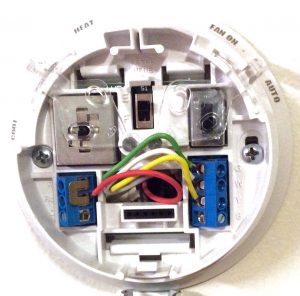
With so many new functions on today’s modern thermostats (t-stats), there is of course, many more wires to connect up. Gone are the two-wire days. Thus we need some soft of color code on the wires to keep all the functions straight. So here, we show examples of the Honeywell thermostat wiring color code for these higher wire count thermostats.
State-of-the-art HVAC systems often include a second stage heater, as well as multiple cooling stages. Many also have a wire to turn on the compressor change over valve. This switches it between heating and cooling mode). Also, there may be a light (L) wire that operates an indicator readout in the t-stat. This light shows heat pump status.
Each of these newer functions must have its own wire to tell the thermostat when to operate. So, these color codes help keep all the wires straight. With them you can avoid matching a wire to the wrong t-tat terminal.
| Wire Color, Typical | Letter Designation | Purpose |
|---|---|---|
| A | Power present here when any heating or cooling is operating in the HVAC system. | |
| Aux/E, W2 | Operates 2nd heating stage, or when controlling a heat pump, the emergency heat stage. | |
| Blue | B | Activates the changeover to heat relay / valves in HVAC systems. |
| Brown, blue, purple, black. | C | 24 volts AC. The common lead of the transformer. All furnace switched components have one side of their power connected to this lead. |
| Brown | E | Activates emergency heat relay |
| Green | G | Operates the internal fan |
| K | May activate emergency heat relay in some installations. Also used between a thermostat and Honeywell wire savers. | |
| L | Heat pump monitor light. May turn on when emergency heat is operating. | |
| Orange | O | Activates the changeover to cool relay / valves in HVAC systems. |
| O/B, W, W1 | Operates first heating stage. For heat pumps, activates the compressor in heat mode. | |
| P | Defrost operation in progress lamp; comes on when either the HVAC compressor outside has switched into defrost mode. | |
| Red | R | 24 volts AC ???? |
| Red | RC | 24 volts AC supply to cooling relay in HVAC system. |
| Red | RH | 24 volts AC supply to heating relay in HVAC system. |
| White | W1, W, O/B | Operates first heating stage. For heat pumps, activates the compressor in heat mode. |
| W2 - Aux/E | Operates 2nd heating stage, or when controlling a heat pump, the emergency heat stage. | |
| X | Malfunction alert lamp. Voltage present when the HVAC system detects a problem in its components. | |
| Yellow | Y1, Y | Operates first stage compressor cooling. |
| Y2 | Operates 2nd cooling stage. | |
| Y, Y1 | Operates first stage compressor cooling. | |
| S1, S2 | Outdoor temperature sensor (S) wires. |
Common Honeywell Thermostat Wiring Color Code
The table above provides a more comprehensive list of Honeywell thermostat wiring colors and their uses. But here is a list of the most common wire color to function mappings. We see this in many three to five wire setups.
-
- C – 24 VAC Common (You might see blue, purple, or brown typically used for this wire).
- G – Fan (green wire). Turns on the circulating fan in most forced air heating and cooling systems. Allows the fan to run independently of whether heating or cooling.
- R – 24 VAC / R and Rc (red). Supplies the high side of the 24 volt AC line from the cooling power transformer in an HVAC system.
- Y – Compressor / cooling (yellow). Turns on the compressor in cooling mode.
- W – Heat (white wire). In gas systems, this triggers the lighting process. It opens the valve, turns on the ignitor, and fires up the burners. In electric furnaces, this lead turns on the heaters. And, in heat pump systems, the white wire starts the compressor.
Warning
For all other t-stat terminals, the exact purpose of a wire may not always be clear.
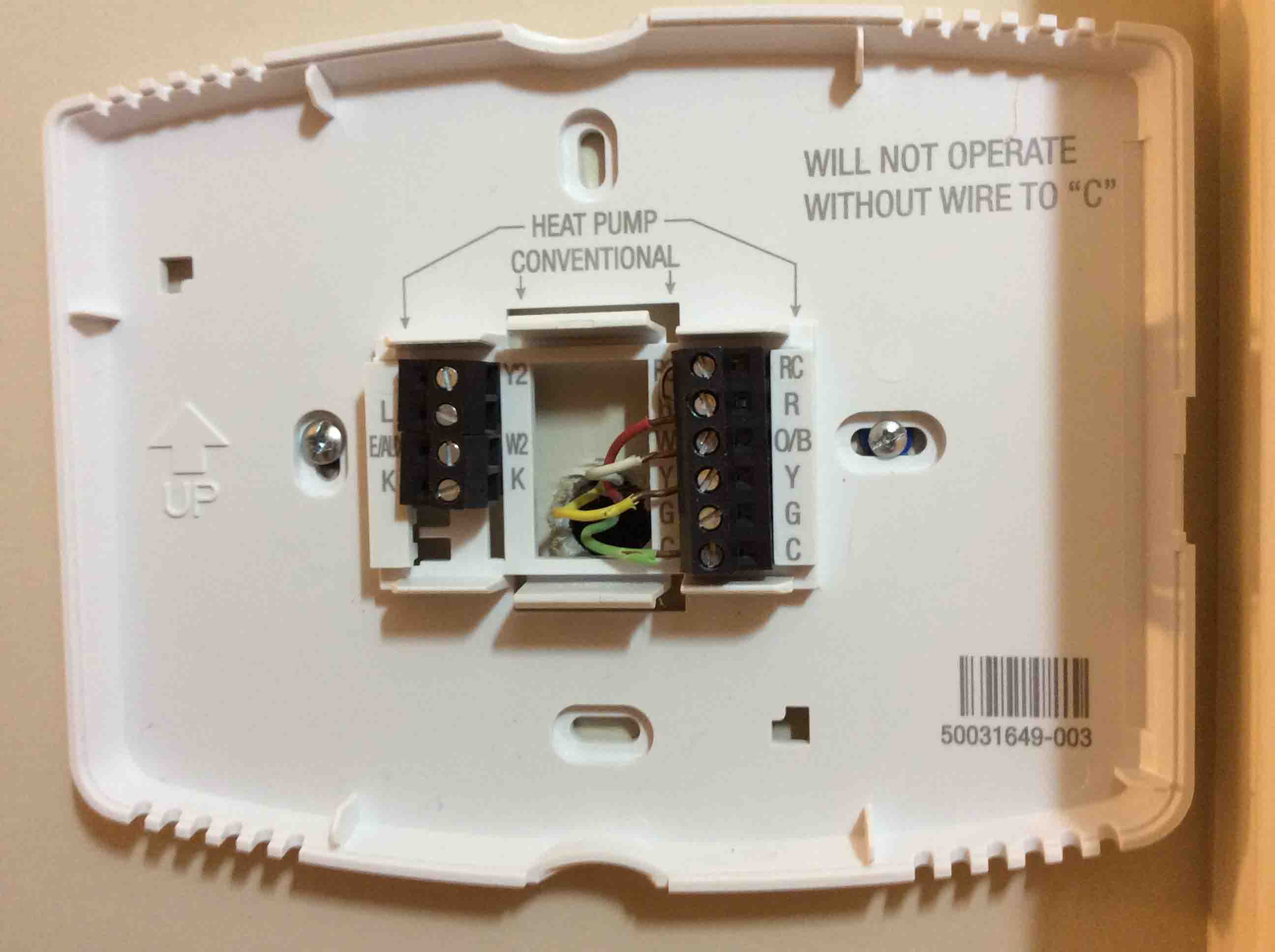
So again, if putting in a new t-tat, DO NOT rely on the wire colors alone! Repeating: DO NOT RELY ON THE WALL WIRE COLORS ALONE TO FIND EXACT WIRE FUNCTION. Instead, take a picture or write down which lug on the old t-stat that each wire goes with. For each wire, jot down its color. Plus, write the letter of the terminal on the old t-stat that it connects with. If the correct wire functions are still not clear, then trace the wires. You need to track the wires back to the HVAC unit itself. Then, find out which parts the various colors of wires attach to.
Do not attempt to wire a t-stat yourself if you feel unsure with working with electricity. Further, wrong wiring can break the t-stat or furnace. This can result in costly repairs.
We cannot assume responsibility for damages due to faulty wiring of any t-stat.